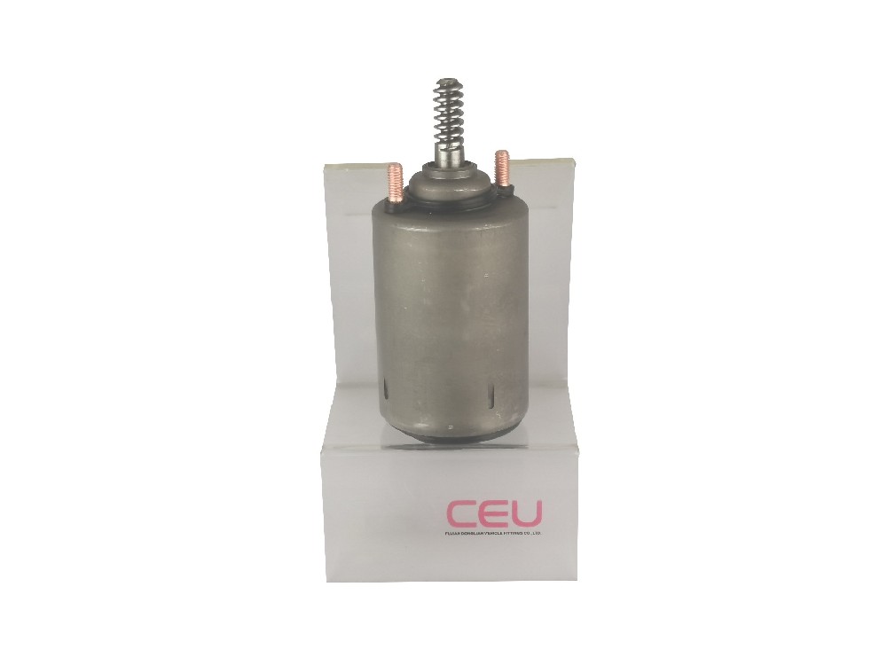
Wiper motor wholesale
Part of the magnetic circuit of the motor, and the stator winding is placed on it.
+86-593-7877777 7877333
 Consult online now
1. The structure of a three-phase asynchronous motor consists of a stator, a rotor and other accessories.
(1) Stator (stationary part)
1. The stator core
Function: A part of the magnetic circuit of the motor, and the stator winding is placed on it.
Structure: The stator core is generally punched and laminated from silicon steel sheets with an insulating layer on the surface of 0.35 to 0.5 mm thick. The inner circle of the core is punched with evenly distributed slots to embed stator windings.
The stator core slot types are as follows:
Semi-closed slot: The efficiency and power factor of the motor are higher, but the winding and insulation are difficult. Generally used in small low-voltage motors. Semi-open slot: It can be inserted into the shaped winding, generally used for large and medium-sized low-voltage motors. The so-called shaped winding means that the winding can be insulated beforehand and then put into the slot.
Open slot: It is used to insert and place the shaped windings, and the insulation method is convenient. It is mainly used in high-voltage motors.
2. Stator winding
Function: It is the circuit part of the motor, which is connected with three-phase alternating current to generate a rotating magnetic field.
Structure: It is composed of three identical windings which are separated by 120° in electrical angle in space and arranged in a row. The coils of these windings are respectively embedded in the slots of the stator according to certain rules.
The main insulation items of the stator winding are as follows: (guarantee reliable insulation between the conductive parts of the winding and the iron core and reliable insulation between the winding itself).
1) Ground insulation: insulation between the stator winding and the stator core.
2) Insulation between phases: insulation between stator windings of each phase.
3) Turn-to-turn insulation: the insulation between turns of each phase stator winding.
Wiring in the motor junction box:
There is a wiring board in the motor junction box, the six wires of the three-phase winding are arranged in two rows up and down, and the three wiring posts in the upper row are numbered 1 (U1), 2 (V1), 3 from left to right. (W1), the three wiring posts in the bottom row are numbered 6 (W2), 4 (U2), 5 (V2) arranged from left to right. Connect the three-phase windings into star connection or delta connection. All manufacturing and maintenance should be arranged according to this serial number.
3. Base
Function: Fix the stator core and the front and rear end covers to support the rotor, and play the role of protection and heat dissipation.
Structure: The frame is usually cast iron, the frame of the large asynchronous motor is generally welded with steel plate, and the frame of the micro motor is made of cast aluminum. There are radiating ribs on the outside of the frame of the enclosed motor to increase the heat dissipation area, and the end caps of the two ends of the frame of the protective motor are provided with ventilation holes, so that the air inside and outside the motor can directly convection to facilitate heat dissipation.
(2) Rotor (rotating part)
1. Rotor core of three-phase asynchronous motor:
Function: As a part of the magnetic circuit of the motor and placing the rotor winding in the core slot.
Structure: The material used is the same as that of the stator, which is punched and laminated with 0.5 mm thick silicon steel sheet. The outer circle of the silicon steel sheet is punched with evenly distributed holes to install the rotor winding. Usually, the inner circle of the silicon steel sheet after the stator core is punched is used to punch the rotor core. Generally, the rotor core of a small asynchronous motor is directly press-fitted on the shaft, and the rotor core of a large and medium-sized asynchronous motor (the rotor diameter is more than 300~400 mm) is pressed on the shaft with the aid of the rotor bracket.